Improving is hard,
Understanding is the key,
Circular logic!
I think I've written about my plans to build another delta printer from scratch before, but I've actually had most of the parts I've needed for close to a year now. I've been holding off this entire time so that I can do it right instead of just mimicing the existing designs that I've found, and one of the issues (admittedly a self-constructed one) has been determining the proper system kinematic parameters. There's an entire field of robotics/mechanisms focusing on the optimization of parallel mechanisms, and there's been plenty of discussion about this on various forums (1,2,3), but I wanted to really break down the kinematics for myself.
I took the details from Steve Graves' Rostock Kinematics Document and implemented the math into a python script that I could more easily adjust and modify. There's also an nice OpenSCAD model by Jay Couture, but I wanted something I could customize and extract numerical data from later. The script describes the performance of the printer in a variety of ways and generates some simple plots to help with visualization. It depends on the numpy and matplotlib Python libraries.
In this entry, I'll focus on just the insight I got from Steve Graves' kinematics document and my Python scripting in terms of how the system parameters affect the performance. Any discussion on optimization can get pretty lengthy, since we can specify our performance metric any number of ways.
Basic Script Usage
It's a pretty basic script that creates 2 Python objects: d for a DeltaPrinter object that provides details about the specified delta, and de for a DeltaError object, which is essentially a pair of deltas that lets us evaluate the effect of errors
> python -i DeltaPrinter.py
>>> d
>>> <__main__.DeltaPrinter object at 0x037CEAD0>
>>> de
>>> <__main__.DeltaError object at 0x037CEB10>
I won't go into detail regarding the implementation, but it should be a carbon copy of the ik and fk described in Graves' kinematics document. There's a helper function genGrid([radius],[step size]) that outputs an n by 2 array of points for testing. For example, genGrid(100,1) generates a grid with -100<x<100 and -100<y<100 and step size 1.
For the DeltaPrinter object, there are 2 primary functions: evaluateStep([points],[plot=False],[sampling=12],[xy step=1]) and evaluateShape([points],[plot=False]). Each function requires an array of points to evaluate. I usually use points from genGrid here, but someone may find it helpful to evaluate the delta performance for a particular trajectory.
For the `DeltaError' object, there's one primary function 'eval([points],[plot=False])' that returns a plot of the errors in the primary cartesian directions across the build space. There's also another plot that details how the error is related to the distance from the build center. For the plots shown below, I'll include the function calls I made to produce them.
Calibration and Leveling
So, I tend to lump both calibration and leveling together for delta printers, since both are done to compensate for kinematic errors. From what I've read (and hopefully I don't cause more confusion), calibration is determining the correct system parameters to input in the firmware, which uses these values to perform inverse-kinematics, and leveling focuses more on the flatness of the print bed relative to the print head. I guess the distinction is a bit important since you can argue that cartesian printers only need leveling, not calibration. In contrast, adjusting the system parameters in the firmware affects the bed levelness relative to the print head. That last bit is important (imo) when describing delta kinematics and also why I lump the two things together.
The full set of adjustable parameters (that I consider) are as follows:
- 3 tower positions (relative to bed center)
- 3 tower endstop locations
- arm length
- carriage offset (displacement between tower and arm joint)
- effector offset (displacement from center to arm joint)
For a reasonably well-built machine, you can make a couple of assumptions:
- tower positions are all a given radius (printer radius) from the center, spaced 2pi/3 (120 degrees) apart
- carriage offsets are all equivalent, with no lateral (side to side) offset relative to the tower center
- effector offsets are all equivalent and can be described as a radius (effector radius)
- arm lengths are all equivalent
- the physical print bed is not warped and is flat relative to the towers
From what I've read from the Repetier firmware, it allows for individual offsets for asymmetric or poor builds, but in my opinion, if it gets to the point where you're actually concerned about that level of adjustment, you should probably rebuild the machine or lower your expectations. For my original Rostock MAX, the leveling/calibration procedure only asked us to tweak the endstops and the printer radius (distance from center to towers). The remaining values were pre-calculated by Seemecnc.
Delta Inverse Kinematics Summary
The key insight (for me) from the Graves' kinematics document was that for a given delta printer, there's an equivalent design with effector and carriage offsets equivalent to 0. The effector and carriage offsets can be restated as a translation of the tower positions to a new set of "virtual" tower positions in a complementary delta that is composed of just these virtual towers and the arms meeting at a single point. This simplifies the system and makes the ik easier to compute. This also means that adjusting the effector or carriage size both have similar effects. If you visualize a delta with an increased carriage offset and an equivalent effector offset decrease, you'll note that the arms should behave in the same way.
Tower Motion Variations Across the Workspace
Overall, especially for those more familiar with cartesian printers, the biggest issue to keep in mind with delta printers is that the carriage motions will vary greatly for the same relative motion depending on where the effector is in the workspace. For example, when you're moving close to a particular tower, the carriage on that particular carriages moves very little, while the opposite is true when you're moving far away from that tower. Evaluating the required movement resolution or max travel of a carriage will factor into our future optimization of a delta design.
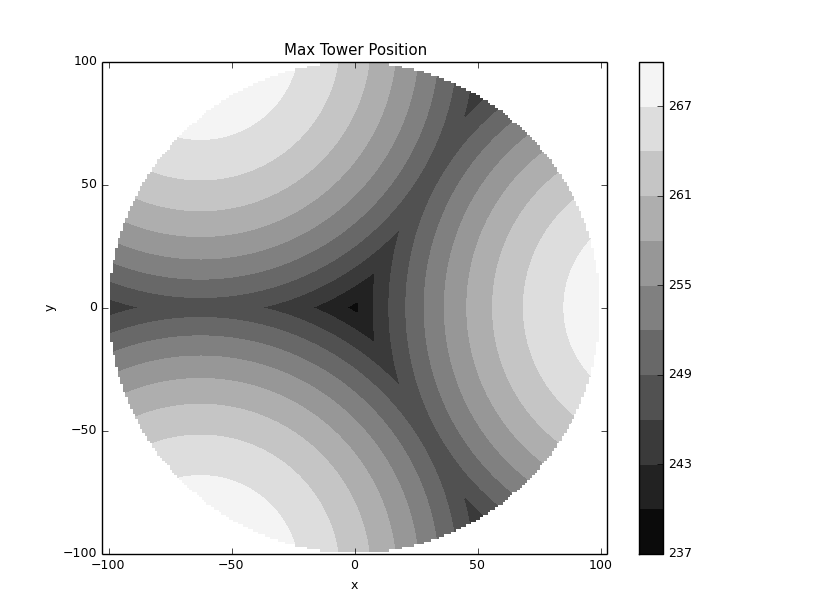
The following plot shows the average tower motion required for a relative unit step move from each point in the workspace. It uses the basic Rostock MAX-esque parameters: printer radius 200mm, build plate radius 125mm. Towers A, B, and C are the towers given in counter-clockwise order, starting with tower A on the far right side of the workspace.
>>> d.evaluateStep(genGrid(125,1),True)
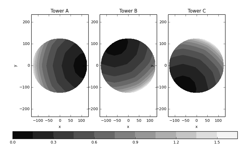
This shows that as you begin to print nearer to the edges of the build plate, especially as it gets very close to the printer radius, there's at least one tower that will need to move more than the commanded cartesian motion. A large necessary motion limits the top speed that the printer can achieve, while a small necessary motion limits the print resolution in that region. As you'd expect, we tend to get a nice, happy average if we commit to only printing in the middle of the workspace:
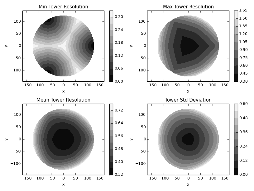
The "Min Tower Resolution" plot is fairly interesting to me. I would argue that we want to either maximize this value or primarily print in regions of the build space where this value is maximized. In those regions, we're maximizing steps/mm in mapping the steppers to the build space. Maximizing this value should increase the achievable resolution.
Print Resolution/Repeatability
In my printer, with belt pitch 2mm, 16 teeth pulleys, 1/16 micro-stepping via the RAMBO board, and standard stepper motors, I should have a tower motion resolution of 10 microns (0.010 mm), according to the Reprap Calculator. Now, I've never asked or looked into how commercial delta printers represent their motion/print resolution, but I do so by introducing an endstop error equivalent to my minimum tower resolution and then look at the corresponding error in the workspace. Some (maybe even most) may argue that I'm really talking about repeatability here, but I'd argue that for the purposes of evaluating the printing capability of a printer, they are more or less the same in this case. I'm not really concerned with mathematically how many encoder steps are used per mm of workspace travel as I am with how robust the printer is to potential stepper errors, due to either control faults or just rounding.
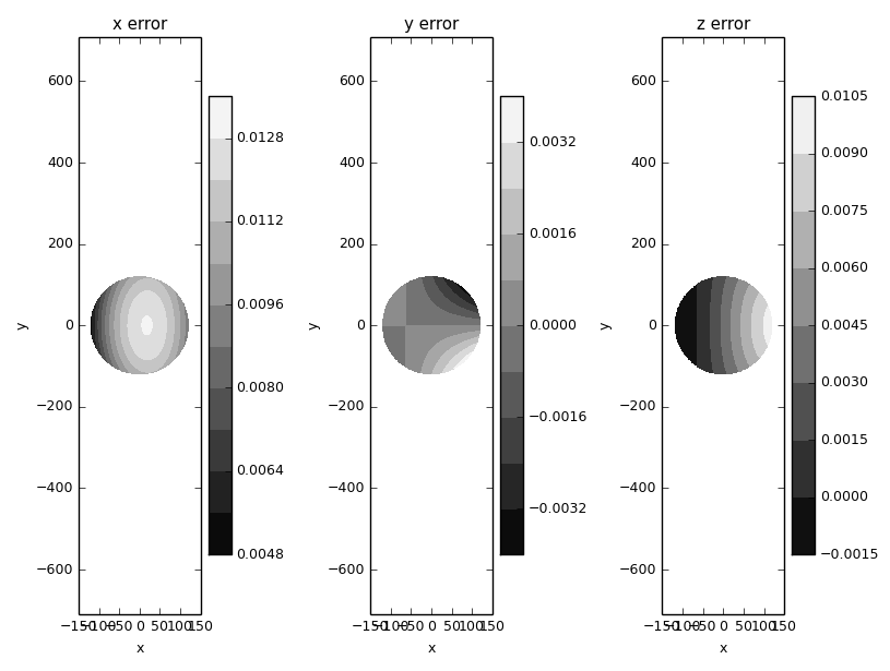
For a positive error in a single tower (A, in this case), we get the following:
>>> de.dTower[0] = 0.01
>>> de.eval(genGrid(125,1),True)
And for the same positive error in 2 towers (A and B in this case), we get the following:
>>> de.dTower[0] = 0.01
>>> de.dTower[1] = 0.01
>>> de.eval(genGrid(125,1),True)
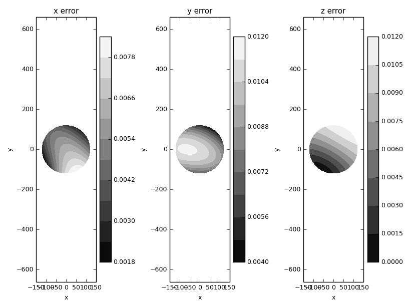
And finally, for a positive error in tower A and a negative error in tower B, we get the following:
>>> de.dTower[0] = 0.01
>>> de.dTower[1] = -0.01
>>> de.eval(genGrid(125,1),True)
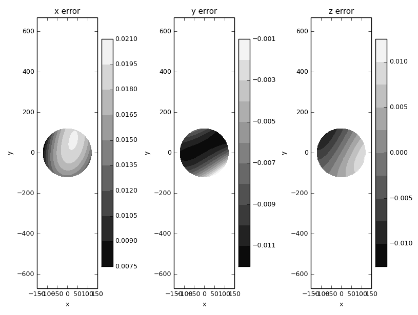
Focusing on the errors in x and y, we see that there's a max of around 21 microns in certain sub-regions. Now, the error I've introduced should be the worst case. I'd guess that the average error due to resolution limitations of the stepper should be a bit lower, but I don't think it's unreasonable to say that this simulation suggests a repeatable movement resolution of at least 25 microns for the entire workspace.
The error in z also validates the (perhaps obvious) leveling suggestion given by many delta manufacturers: to calibrate/set the endstop for a given tower, measure the offset between the nozzle and the bed directly in front of the tower. We can see that it approximates our artificially introduced error quite closely.
Workspace Limits and Shape
The arm length selection affects the amount of "wasted" or "unusable" print space as well as the necessary range of allowable joint angles at the arm ends. Assuming that we only want a workspace where we can fully print in xy for some height, then the max tower height calculated for a desired xy-plane at height z=0 should give us the "wasted" height in z. The overall delta height minus this value should then give us the max z height that's printable:
>>> d.evaluateShape(genGrid(100,1),True)
For joint angles, I measured the angles relative to the initial joint value with the effector at x=0,y=0. Elevation is the angle measured between the build plane and the arm, and azimuth is the projected angle you'd see if you looked down at the effector from above:

There shouldn't be any major surprises here. We should expect to need more travel in z and in the joint angles for the boundaries of our workspace. I don't know if or how other delta designers have decided on their build plate sizes, but it looks like it'd be beneficial to build a fatter/wider delta for a smaller working print space. I think it's pretty common to hear of the average user struggling to properly print across the full extent of the build plate. Usually the suggested answer is to just level/calibrate better, but I would argue that it's at least partially the responsibility of the original engineer to specify parameters for a design that's robust to potential errors in assembly and/or operation.